
- #Raspberry pi eeprom programmer install#
- #Raspberry pi eeprom programmer serial#
- #Raspberry pi eeprom programmer update#
In that case, the above commands will update it to the latest version.
#Raspberry pi eeprom programmer install#
To install RPi.GPIO python library, type the following commands on terminal window of your Raspberry Pi −Īlmost all the latest versions of distributions have RPi.GPIO already installed. To set up the output of GPIO pins and to read the input values by using Python, you need to install RPi.GPIO python library. You should not try to draw more than a total of 50mA from the 3.3V supply pins.


Don’t try to provide more power than that. You should not poke the GPIO connector with a screwdriver when the Raspberry Pi board is powered up.ĥV power is enough for your Raspberry Pi. Although, you can draw more but to increase the life of your Pi Board, you should restrict upto 3mA.
#Raspberry pi eeprom programmer serial#
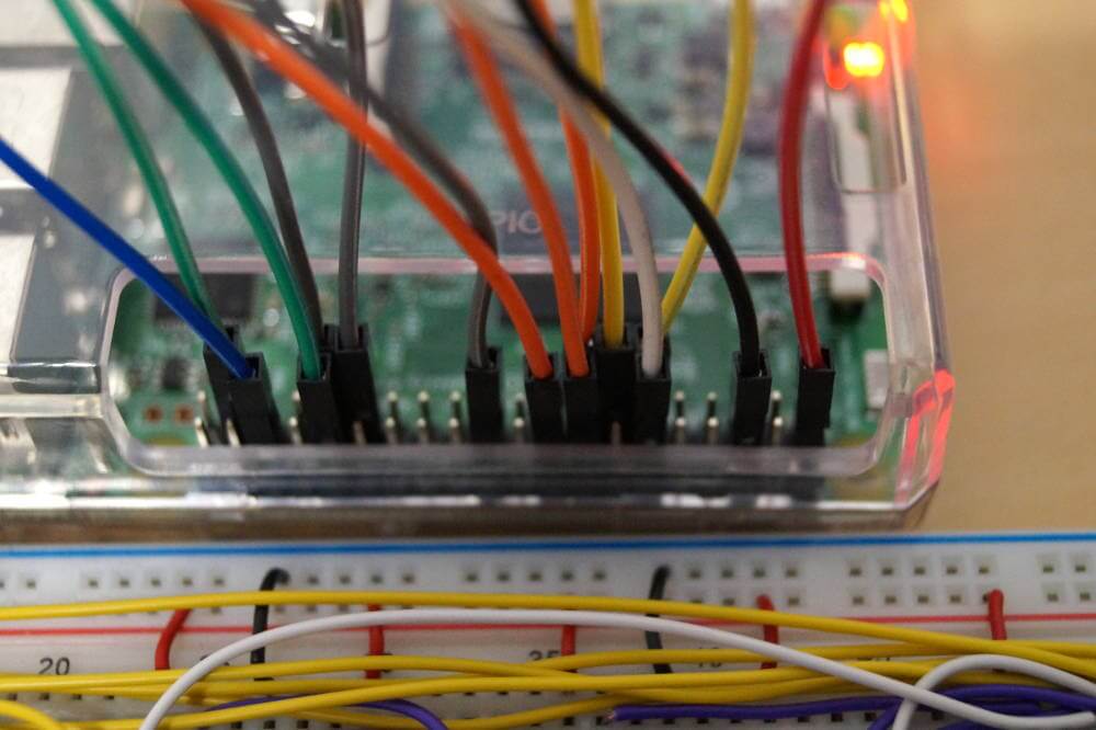
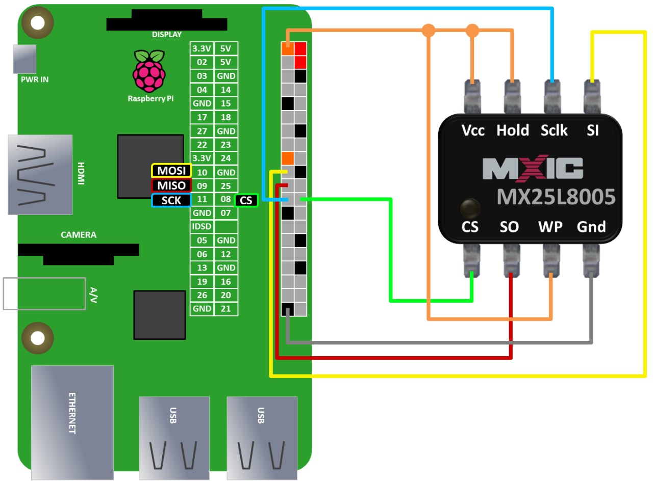
The serial function is available at the following −įollowing are some simple rules to reduce the risk of damaging your Raspberry Pi board, while using the GPIO connector −ĭo not try to put more than 3.3V on any GPIO pin.ĭo not try to draw more than 3mA per output. SPI1: MOSI (GPIO20) MISO (GPIO19) SCLK (GPIO21) CE0 (GPIO18) CE1 (GPIO17) CE2 (GPIO16)ĮEPROM Data: (GPIO0) EEPROM Clock (GPIO1) SPI0: MOSI (GPIO10) MISO (GPIO9) SCLK (GPIO11) CE0 (GPIO8), CE1 (GPIO7) Software PWM are available on all the pins whereas Hardware PWM are available on GPIO12, GPIO13, GPIO18, and GPIO19. Among them, some are available on all pins and others on specific pins. GPIO pins can be used with a variety of alternative functions. You can see in the above diagram, GPIO2 and GPIO3 pins have fixed pull-up resistors but for the other pins, you can configure it in software. You can use internal pull-up or pull-down resistors. The pin set as input pin can be read as 3V3(high) or 0V(low). InputsĪ GPIO pin can be designated as an input pin. The pin set as output pin can be set to 3V3(high) or 0V(low). OutputsĪ GPIO pin can be designated as an output pin. One of the powerful features of the Raspberry Pi is the row of GPIO (general-purpose input output) pins and the GPIO Pinout is an interactive reference to these GPIO pins.įollowing diagram shows a 40-pin GPIO header, which is found on all the current Raspberry Pi boards −įrom the above diagram, we can see that there are two 5V pins and two 3V3 pins on the board. Here, we will learn about the GPIO (general-purpose input output) connector in Raspberry Pi.


 0 kommentar(er)
